
The same reason water floats our boats also slows them down. Water is dense. Pushing a hull through the water, and maintaining planing speeds, requires an appreciable amount of power. The resistance profile of a hull is easily predicted. And the magnitude of thrust is eye-opening when compared to, say, a car on pavement going the same speed. At planing speeds, 50 miles per hour for example, the required power to propel a hull in water can be orders of magnitude greater than that of a car going the same speed on a road. It a drag, for sure, so how can we deal with it best?
Planing hulls progress through displacement mode, then need to overcome hump, which is where resistance is maximum, then operate on plane. Planing takes place when hydrodynamic forces overcome static, or buoyant, forces. Let consider a 60-foot flybridge sportfishing yacht. Total resistance is comprised of the following components:
- Bare hull drag
- Appendage drag
- Air drag
Bare hull resistance is driven by hull shape and vessel weight and LCG. As we have discussed before, proper hull form is critical and is heavily dependent on expected operational speeds. Bare hull resistance is also impacted by sea state. Usually, performance is thought of in calm water with waves increasing drag. Water depth can also be a factor so true performance should be assessed in deep water, about two thirds of the running surface length or more.
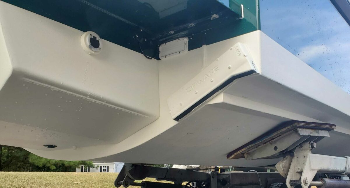
Appendages are a significant player in adding to the total resistance of the hull. Shafts, propellers, rudders, water intakes, keels, transducers and other required items all create drag. Proper geometry and arrangement of these items is important in minimizing their impact on performance. On high performance hulls, a feature like a sea chest can help greatly by getting rid of the use of multiple draggy sea water pickups.
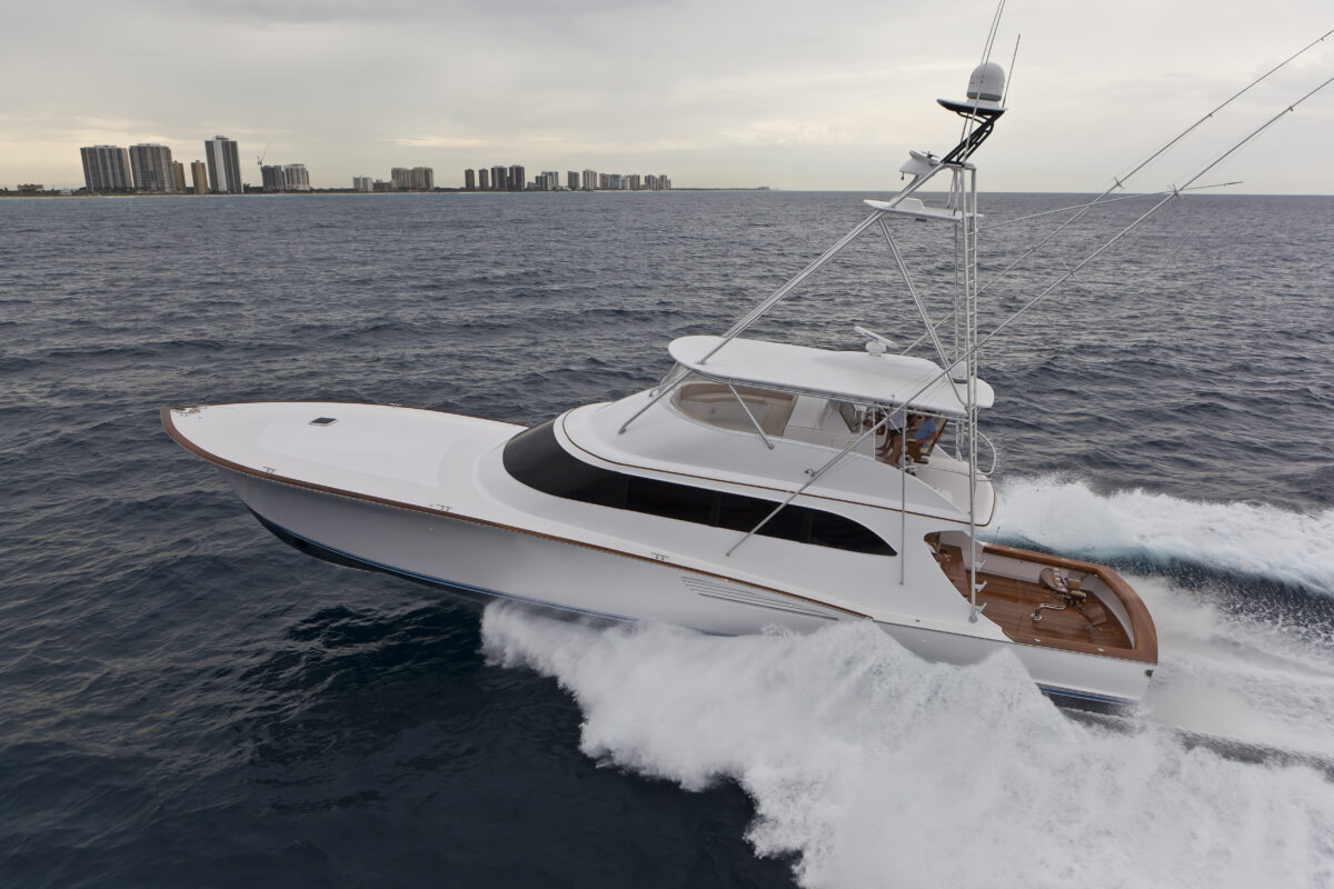
Air drag becomes a larger player in the total resistance profile as speed increases. Air drag is important but, for the reason mentioned at the beginning of this discussion, not nearly as impactful as underwater appendages. But as speeds get higher and higher, air drag becomes a higher percentage of the total. Deck and deckhouse geometry, hardtops, eisenglass, windscreens and towers have differing impacts.
Looking at our 60-foot sportfish running at 45 knots, typical appendage drag, representing propellers on inclined shafts, with struts and rudders, adds 10 percent to 15 percent to the bare hull resistance. Air drag caused by the deckhouse and bridge can mean an additional 10 percent hit. A full tuna tower can add yet another 10 percent by itself. All these added together means were adding approximately 35 percent more resistance to our bare hull. These all need to be accounted for when predicting speeds and sizing drivelines.
But we cant just not have appendages or desired deck features. So how can we try to minimize these drag inducing variables? First, hull form, and proper hull type, are absolutely critical. And keeping that bottom clean is important. That means minimizing the number of appendages, optimizing their design and keeping marine growth to a minimum. Quality bottom paint and proper application can make an appreciable difference as well.
A somewhat new technology being seen quite a bit lately is wake-adjusted running gear. With these, a computer simulation using computational fluid dynamics allows the designer to create shapes for the strut, rudder and propeller, which are more slippery in the predicted water flow for the given hull geometry. CFD can also allow for a more detailed optimization of hull features like keel pads, propeller tunnels and strakes. On very high-speed hulls, especially larger, fast motor yachts, CFD is also used to optimize predicted air flow around deck features so that air drag is minimized.
Shaft tubes have become somewhat common, especially on custom builds. These tubes cover the rotating shaft removing the Magnus Effect. This effect occurs when a cylinder (shaft) rotates in a fluid. This rotation causes pressure differences on opposite sides of the shaft, generating a force mostly perpendicular to the shaft, thus increasing drag. The fixed tube, while a larger diameter, removes this induced drag.
Hull features can be added to help generate lift, which also helps to reduce overall resistance. Strakes, when properly designed and located, help to reduce wetted surface, reducing bare hull resistance. Maintaining sharp edges at the chine and strakes, and at the hydrodynamic transom promotes clean flow separation at planing speeds, also reducing drag.
For high performance hulls, these items become more and more important as speed increases. Any one detail may not have an appreciable impact. But combining several, or all, of these will have a significant impact in reducing overall resistance. And for a given installed horsepower, lower resistance means more speed and better fuel burn”two features most everyone can agree are necessary.
Originally from Annapolis, Chris moved from aerospace to the marine industry early in his career. For more than twenty years, he has taken pride in being able to build lasting relationships with many world-class yacht builders. He has managed countless new designs and builds, including patrol and rescue craft, production boats and high-end custom sportfishing yachts, with a design focus on high-performance, hydrodynamics, hull forms and structures.